Wow, it’s been a long time since I’ve posted. I have been knee-deep in studying for my CCIE R&S, learning my new environment at my new job, and being a father to my newborn son.
I will start the New Year with something new I learned at my job: how a Cisco ACE works and the configuration behind one.
At first, I was going to make this a two-part post, but seeing as how massive this post is going to be, I am going to split it up into three,
- What is an ACE
- Basic ACE configuration
- ACE load balancing configuration
What Is a Cisco ACE?
A Cisco ACE (Application Control Engine) is a load balancer. A load balancer is a product that evenly distributes the load to multiple servers instead of one server getting hit. It is configured with Virtual IP addresses that map to what is known as “reals” or real servers and will balance the load to all the reals however you have it configured to do so. Some of the balancing predictors are;
- Round-Robin (default)
- Least Connections
- Least Bandwidth
- Least Loaded
- Least Connections
- Application Response
- Hash Address
- Hash Content
- Hash Cookie
- Hash Header
- Hash URL
The ACE also has redundancy; you can create an FT (Fault Tolerance) group, allowing multiple ACE appliances/modules to use the VLAN as a heartbeat. If the standby ACE does not hear from its peer, the device will fail. It can go from the ACE in the same switch (standalone or VSS) or on opposite sides of the data center.
ACE monitors server health by using probes. Probes can be configured to watch a specific port or page on the website. If it can’t reach the port or can’t GET the page, the following will happen;
the ace will try to contact the probe type every x seconds as listed in the interval value. It will mark the real server as bad after the fail detects value. At this point, the ACE will start a timer called pass detect. Once this timer expires, the ACE will try to use the probe; at this point, before the probe becomes valid again, it needs to satisfy the pass detect count value, so let’s look at a sample configuration.
probe http TEST
interval 5 # probe sent every 5 seconds
faildetect 4  # 4 missed probes will bring real down (20 seconds)
passdetect interval 30 # ace will wait 30 seconds before trying to probe that down real server
passdetect count 4 # probe needs to be successful 4 times to bring real back online
You can set the ACE up in one of three different modes:
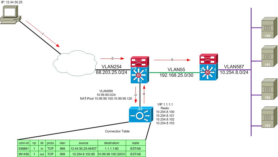
One-arm mode with Source NAT allows you to NAT all incoming connections to the ACE. This is more scalable if you have a more extensive infrastructure. With this design, your real servers can be sitting anywhere if you have layer 3 reachability with the source-nat address specified in the configuration. Only 1 VLAN interface is configured in this mode.

The above picture shows the following.
- User requests https://1.1.1.1
- The packet arrives at our internet edge router. There is a route saying for network 1.1.1.0/24 to route the packet to the next-hop IP 10.99.99.23
- The packet arrives at the ACE, and the ACE makes a forwarding decision on where to send the packet based on the VIP, and the real server to the ACE is forwarding the traffic. Note the ACE has a 0.0.0.0 0.0.0.0 route pointing to 10.99.99.1
- The packet is sent to 10.99.99.1 with a source of 10.254.8.102 and a destination of 10.99.99.100 instead of 12.44.50.25
- The packet flows like a normally routed packet in your network.
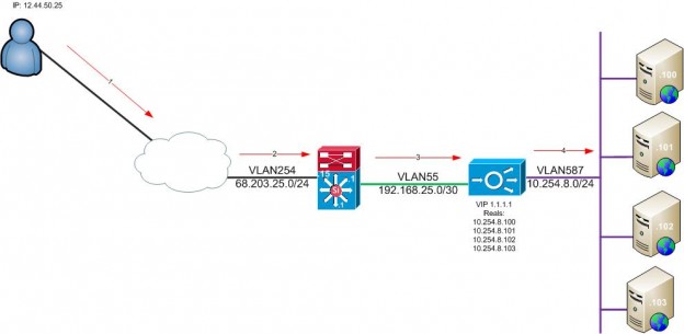
Routed Mode- the ACE acts as a router. You have two VLAN interfaces configured in this mode, one where the clients will hit first, and the second is the server VLAN. This way is good for a smaller environment. Once you run out of room on the server’s real VLAN, you must create a new context or install a new ACE. There are two VLANs configured on the ACE in this mode.

- User requests https://1.1.1.1
- The packet arrives at our internet edge router. There is a route saying for network 1.1.1.0/24 to route the packet to the next-hop IP 192.168.25.5
- The packet arrives at the ACE, and the ACE makes a forwarding decision on where to send the packet based on the VIP, and the real server to the ACE is forwarding the traffic. Note the ACE has a 0.0.0.0 0.0.0.0 route pointing to 192.168.25.1
- The packet is sent to 10.254.8.102 because it is a connected route to the ACE and forwarded to its destination.
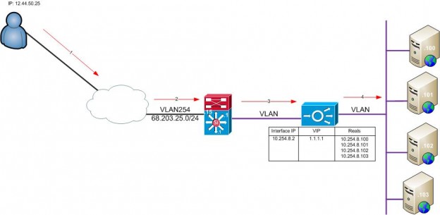
Bridge Mode – Operates in the same fashion as you would set up a Cisco WAP using a BVI. The Bridge Virtual Interface ties the two VLANs together using a bridge group. Only a 0.0.0.0 0.0.0.0 static route toward the MSFC for outbound traffic. Two-layer 2 VLANs are created and tied together by a BVI.

- User requests https://1.1.1.1
- The packet arrives at our internet edge router. There is a route saying for network 1.1.1.0/24 to route the packet to the next-hop IP 10.254.8.2
- The packet arrives at the ACE, and the ACE makes a forwarding decision on where to send the packet based on the VIP and the real server to the ACE is forwarding the traffic.
- The ACE sees that the REALs are on the same VLAN, sending the frames to the correct server.
The next post will be putting a basic configuration on a Cisco ACE.