.I came across a new topic while studying for DCUFI. The topic I was most excited to read about is Unified Fabric! I am going to share some of what I learned in this post.
Unified Fabric is a term that aims to reduce cabling in the data center. When you provision a new server or chassis, you can run 1 or 2 cables instead of 2 or 4. Unified Fabric unifies the Ethernet and Storage networks by utilizing FCoE, 10Gigabit Ethernet, and a new Converged Network Adapter, AKA the CNA.

The CNA can be a single or a dual-port card, and it processes Fibre Channel and Ethernet. But wait one second, this is a unified fabric posting; why does the CNA understand Fibre Channel? Shouldn’t it speak FCoE? Well, therein lies the magic of the CNA; let’s look at one from a fundamental standpoint.
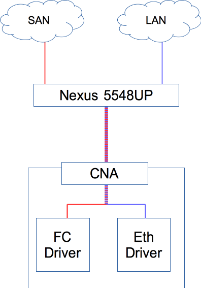
As depicted above, the CNA has an FC driver and an Ethernet Driver. From the point of view of the Nexus 5548, it is sending FCoE traffic down to the CNA. It is the responsibility of the CNA to decode and decipher what it will do with the frame. It decides to send it to the FC driver or the Ethernet driver.
As depicted in the diagram, from the 5548, only one cable is running to the CNA. You usually want two for SAN and LAN redundancy, but we have a unified fabric.
With the advent of Unified Fabric, a few other Data Center Bridging (DCB) standards have been introduced. Some of them add some elegant new features to some old tried and true network concepts;
Priority Flow Control (802.1Qbb) – Before we examine PFC, we first need to understand flow control. Flow control is a mechanism where the receiving switch stops transmission from the sending station’s other side, sending data faster. You only have to worry about this if you have a faster interface sending to a slower interface—for example, 10G to 1G. Let us look at the diagram below.

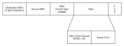
What we see is Switch 1 is sending data at a rate that Switch 2 can not handle. Switch 2’s ingress buffers are getting full at too fast a rate. Switch 2 sends a PAUSE frame to Switch 1, which looks like the following.

It will pause all the traffic, which needs to be retransmitted somehow. In the case of TCP, this is done via TCP retransmission, but in UDP, you will lose all the packets that get paused.
What if there was a way to limit a specific CoS value from sending but allow other CoS values to send? This is where Priority Flow Control (PFC) comes in. What Priority Flow Control does is it can pause based on CoS values. Now, you can designate CoS values never to be paused or values that will pause once they are at a certain level. Once it recovers from the pause time, the traffic for that CoS value will flow again.
The next piece of DCB is ETS or Enhanced Transmission Selection. You assign the amount of bandwidth a specific CoS class can use and give that class a certain percentage of bandwidth. Let’s say you allocate bandwidth based on the following.
CoS 3,4 and 5 are not transmitting, and CoS 2 needs to exceed 10%. As long as the higher CoS values do not need the bandwidth, CoS 2 can borrow from CoS 3, 4, and/or 5. Once one of the higher CoS values does want to transmit data, CoS 2 must slow down to its minimum. Now, the higher CoS value that wants to send data can start.
The next piece of DCB is DCBX, or Data Center Bridging Exchange. This utilizes LLDP and allows switches to discover each other and what their DCB capabilities are. It will allow for configuration replication between neighbors for DBC protocols so that all devices are in sync.