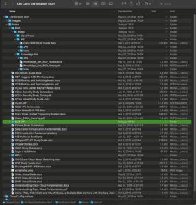
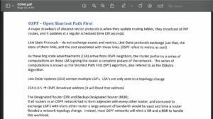
Let’s take a trip down memory lane. I last learned about OSPF basics when studying for my ICND 2 exam in 2008. How do I know and or remember this? Well, 1, it was when I earned my CCNA, my first-ever associate Cisco certification. The more plausible answer is that I kept all my notes and looked at the file’s date. Not to go too off track, but here is the directory that most of my notes are in and a screenshot of my OSPF notes from my ICND2 study guide.


And yes, I did crop the notes so the words FRAME RELAY wouldn’t show up and send people into a downward spiral. You are welcome. I know what networking-related PTSD can surface from that.
This post is meant to be a refresher for those who have not looked at OSPF in a long time and those who might be starting out wanting to learn more. We will start with the basics in this post and throughout the rest of the blogs as we build the underlay. I will let you know if we modify any configuration that we completed in case you are following along at home. One of my pet peeves is going through a tutorial, and they forget to tell you that they completely changed around the configuration, leaving you scratching your head and going, “Um. How did that happen?.?.???…”
Without any further adieu…..
What is OSPF
OSPF, or Open Shortest Path First, is a link-state routing protocol. OSPF will exchange information about the states of its links to neighbors, and this link state information is stored in the Link State Database or LSDB. This exchange of information is done via Link-State Advertisements or LSAs. In contrast to other routing protocols like distance vector, you are computing the distance or cost from you to the networks your directly connected neighbors send you. Distance Vector protocols expect routing updates at specific intervals where link-state protocols will update if there is a change to any of the links.
You will sometimes hear that Distance vector protocols perform something called “Routing by Rumor.” The routers do not know that a neighboring router has the 100% absolute best path to a destination.
There is a routing protocol type called Path Vector. This is the fancy name for BGP. A path vector routing protocol maintains the path information and gets dynamically updated by its peers. We will look at several “flavors” of BGP throughout this series.
OSPF Basics
OSPF Neighbor Types
Boy, I am glad this isn’t the mid-2000s when I was first learning about OSPF. I would have to go into a few OSPF network types that made me want to give up on networking and forget about if you forgot to put the word broadcast at the end of the Frame-Relay DLCI statement. Today, the network types are easy and straightforward. Typically, today you will see one of these two networks:
- Broadcast: Typically used on a shared network segment where you need to have a Designated Router (DR) or Backup Designated Router (BDR) selected
- On a broadcast network, a DR and BDR are elected. The BDR is only ever promoted to DR if the current DR goes down. This DR device controls the synchronization of the LSDB on a multi-access network, i.e., devices connected on the same LAN. This election process looks at the following:
- Highest OSPF Priority on a specific segment
- Highest Router ID
- On a broadcast network, a DR and BDR are elected. The BDR is only ever promoted to DR if the current DR goes down. This DR device controls the synchronization of the LSDB on a multi-access network, i.e., devices connected on the same LAN. This election process looks at the following:
- Point-to-point: Used on links where there will only ever be one neighbor
There is also
- Non-Broadcast: used on non-broadcast networks, and you have to specify the neighbors manually
- point-to-multipoint: used on a hub and spoke style network.
Authentication is also supported using simple (clear text) passwords or MD5 hashes.
OSPF Hello and Dead Timers
OSPF will send out hello packets to all directly connected neighbors on all OSPF listeners’ multicast address, which is 224.0.0.5. This is done to ensure that the neighbor is still up and during the neighbor negotiation process. If on a multi-access network where a DR/BDR is elected, all routers send updates to the DR/BDR on multicast address 224.0.0.6.
The interval for this depends on what kind of neighbor is set up. Only focusing on the ones you will see in mostly today’s networks, both broadcast and point-to-point network types, your hello and dead timer by default is 10/40. This can be modified at the interface level with ip ospf hello-interval {seconds} or ip ospf dead-interval {seconds}. Configuring one will also configure the other, meaning if you configure the hello interval, the dead interval will be automatically computed to be 4x that value and vice versa.
OSPF Area and Area Types
When you create an OSPF network, you split it into areas, with area 0 being the backbone area. This is done to limit the network’s reprocessing if the OSPF topology changes. Other areas are updated about the change via the Area Border Router (ABR) or the Area Autonomous System Boundary Router (ASBR).
Since this is a quick refresher to OSPF, we will not be diving into this or Not-So-Stubby Areas (NSSAs). If this is of interest, let me know, and I will go more in-depth.
OSPF Interface States
When you look at show ip ospf neighbor you will see the interfaces transition through a few different states. The states that an OSPF interface can be in are:
- Down – No hellos have been received from the neighbor
- Attempt – Unicast hello packets sent to the neighbor. This is only seen on non-broadcast OSPF networks where you have to specify the neighbor address manually
- Init – First packet received from that neighbor
- 2way – Each router has received a hello packet that contains its own Router Identifier. This means that 2-way or bi-directional communication is in place
- EXSTART – Exchange of link state database. The highest OSPF Router ID will determine who sends the first packet
- EXCHANGE – Database descriptor packets are exchanged. This is essentially a copy of the local router link state database
- Loading – The router sends link state requests (LSR) packets to potential neighbors
- Full – Databases are synchronized between neighbors, and the OSPF adjacency is formed
OSPF LSA
This is an integral part of OSPF, and I do not want to show it any disservice. Since this is an “intro,” I will touch on the different LSA types. If you want to dive deeper, I can post another on all the different LSA types and what they look like. There are 8 LSA types, they are:
- LSA Type-1: Router LSA: The directly connected links on a router
- LSA Type-2: Network LSA: Generated by the DR and advertised to all routers on the multi-access network
- LSA Type-3: Summary LSA: If you summarize routes at area border routers, this LSA will propagate into the Adjacent area. These routes will be seen as O IA in the routing table.
- LSA Type-4: Summary ASBR LSA: The router doing the redistribution into OSPF will generate a type 4 LSA to let other routers in other areas know that this is the router doing the redistribution between routing protocols
- LSA Type-5: Autonomous System External LSA: This is the same as Type-3, except there is redistribution happening in the source area, so these redistributed routes are tagged differently as they go through the area border router
- LSA Type-6: Multicast OSPF LSA: Used with Multicast OSPF for multicast group memberships.
- LSA Type-7: Not So Stubby Area LSA: If an area is configured as a Not So Stubby Area (NSSA) instead of Type 5 LSAs being used inside that area, Type 7 LSAs are used. Once it crosses the area boundary, it changes to a Type 5 LSA
This series will focus on the Router LSA, as we will not have a multi-area OSPF setup or a DR on any segment.
Configuring OSPF
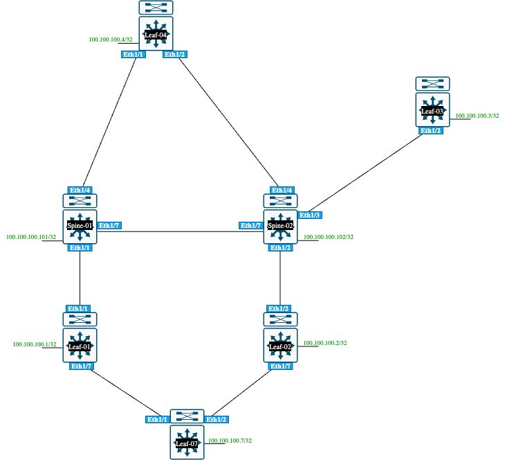
OK, it’s the time everyone has been waiting for! We are going to configure OSPF on parts of our lab. The topology is below:

The devices that we are going to use in this lab are Nexus 9300s. Configuring OSPF is different from doing it on IOS-XE or IOS-XR because who needs uniformity?
I am going to show the configuration on two devices because there will be a lot of duplication. We are going to configure Spine-01 and Leaf-01.
Spine-01 Configuration
Spine-01# conf t
Enter configuration commands, one per line. End with CNTL/Z.
# Set Interface Configuration
Spine-01(config)# interface eth1/1
Spine-01(config-if)# no switchport
Spine-01(config-if)# ip address 10.0.0.1 255.255.255.252
Spine-01(config-if)# no shut
Spine-01(config-if)# exit
Spine-01(config)# int loop0
Spine-01(config-if)# ip address 100.100.100.101 255.255.255.255
Spine-01(config-if)# exit
# Enable OSPF
Spine-01(config)# feature ospf
# Configure OSPF Process and put interfaces into Area 0
Spine-01(config)# router ospf 100
Spine-01(config-router)# router-id 100.100.100.101
Spine-01(config-router)# exit
Spine-01(config)# interface eth1/1
Spine-01(config-if)# ip router ospf 100 area 0.0.0.0
Spine-01(config-if)# ip ospf network point-to-point
Spine-01(config-if)# interface loop0
Spine-01(config-if)# ip router ospf 100 area 0.0.0.0
Spine-01(config-if)# end
Spine-01#
Leaf-01 Configuration
Leaf-01# conf t
Enter configuration commands, one per line. End with CNTL/Z.
# Set Interface Configuration
Leaf-01(config)# int eth1/1
Leaf-01(config-if)# no switchport
Leaf-01(config-if)# ip address 10.0.0.2 255.255.255.252
Leaf-01(config-if)# no shut
Leaf-01(config-if)# int loop0
Leaf-01(config-if)# ip address 100.100.100.1/32
Leaf-01(config-if)# exit
# Enable OSPF
Leaf-01(config)# feature ospf
# Configure OSPF Process and put interfaces into Area 0
Leaf-01(config)# router ospf 100
Leaf-01(config-router)# router-id 100.100.100.1
Leaf-01(config-router)# exit
Leaf-01(config)# int eth1/1
Leaf-01(config-if)# ip ospf network point-to-point
Leaf-01(config-if)# ip router ospf 100 area 0
Leaf-01(config-if)# int loop0
Leaf-01(config-if)# ip router ospf 100 area 0
Let’s do some verifications to see how we can look at the database and how to interpret some of these show commands.
Verifications
Leaf-01# show ip ospf neighbor
 OSPF Process ID 100 VRF default
 Total number of neighbors: 2
 Neighbor ID     Pri State            Up Time  Address         Interface
 100.100.100.101   1 FULL/ -          01:26:02 10.0.0.1        Eth1/1
 100.100.100.7     1 FULL/ -          00:13:00 10.0.0.22       Eth1/7
show IP ospf neighbor
You can add detail to the end of it to get a lot more information, like how many state changes, what area the link belongs to, interface addresses, when the next dead timer is due, etc.
Leaf-01# show ip ospf interface brief
 OSPF Process ID 100 VRF default
 Total number of interface: 3
 Interface               ID     Area            Cost   State    Neighbors Status
 Eth1/1                  1      0.0.0.0         40     P2P      1         up
 Eth1/7                  3      0.0.0.0         40     P2P      1         up
 Lo0                     2      0.0.0.0         1      LOOPBACK 0         up
Show ip ospf interface { brief }
Reading the Link State Database
If you can master reading the Link-State Database, you are Yoda! Because we are in the same area, we are only going to look at a few different ways to read the LSDB, that is, from the router LSA type, what the router is self-originating, as well as the LSAs for the whole area.
show ip ospf database router
Leaf-01# show ip ospf database router
        OSPF Router with ID (100.100.100.1) (Process ID 100 VRF default)

                Router Link States (Area 0.0.0.0)

Link ID         ADV Router      Age        Seq#       Checksum Link Count
100.100.100.1   100.100.100.1   231        0x8000000b 0xcefd   5
100.100.100.2   100.100.100.2   1140       0x80000007 0x8c15   3
100.100.100.3   100.100.100.3   803        0x80000008 0x4e37   3
100.100.100.4   100.100.100.4   900        0x80000007 0x382f   5
100.100.100.7   100.100.100.7   236        0x80000006 0xf987   4
100.100.100.101 100.100.100.101 902        0x8000000a 0x7b59   7
100.100.100.102 100.100.100.102 804        0x8000000c 0x0ce1   9
This shows all of the OSPF-speaking routers’ link states.
You can also take a specific router and see what that device is advertising with its effective cost.
Leaf-01# show ip ospf database router adv-router 100.100.100.7 detail
        OSPF Router with ID (100.100.100.1) (Process ID 100 VRF default)

                Router Link States (Area 0.0.0.0)

   LS age: 332
   Options: 0x2 (No TOS-capability, No DC)
   LS Type: Router Links
   Link State ID: 100.100.100.7
   Advertising Router: 100.100.100.7
   LS Seq Number: 0x80000006
   Checksum: 0xf987
   Length: 72
    Number of links: 4

     Link connected to: a Router (point-to-point)
     (Link ID) Neighboring Router ID: 100.100.100.1
     (Link Data) Router Interface address: 10.0.0.22
       Number of TOS metrics: 0
         TOS   0 Metric: 40

     Link connected to: a Stub Network
      (Link ID) Network/Subnet Number: 10.0.0.20
      (Link Data) Network Mask: 255.255.255.252
       Number of TOS metrics: 0
         TOS   0 Metric: 40

     Link connected to: a Stub Network
      (Link ID) Network/Subnet Number: 10.0.0.24
      (Link Data) Network Mask: 255.255.255.252
       Number of TOS metrics: 0
         TOS   0 Metric: 40

     Link connected to: a Stub Network
      (Link ID) Network/Subnet Number: 100.100.100.7
      (Link Data) Network Mask: 255.255.255.255
       Number of TOS metrics: 0
         TOS   0 Metric: 1


Leaf-01#
There are a few things to point out here. This is from the point of view of Leaf-07, so you see that he is connected to R1 (Neighboring Router-ID: 100.100.100.1), and the interface used to connect to Leaf-01 is 10.0.0.22. Stub networks that have a metric of 40 are transit networks. These routes are just used to propagate routes. Stub networks are also loopback interfaces. By looking at this, if we wanted to calculate the cost of the path between Leaf-01 and the loopback interface on Leaf-07, we can deduce that the cost would be 41, 40 for the link between Leaf-01 and Leaf-07, and 1 for the cost to the loopback. We can compare this via the routing table by looking at the OSPF route for 100.100.100.7
Leaf-01# sh ip route 100.100.100.7 | beg 100
100.100.100.7/32, ubest/mbest: 1/0
    *via 10.0.0.22, Eth1/7, [110/41], 00:43:20, ospf-100, intra
If we want to look at what we are including in our router LSA, we can issue show ip ospf database router self-originated detail
Leaf-01# show ip ospf database router self-originated detail
        OSPF Router with ID (100.100.100.1) (Process ID 100 VRF default)

                Router Link States (Area 0.0.0.0)

   LS age: 845
   Options: 0x2 (No TOS-capability, No DC)
   LS Type: Router Links
   Link State ID: 100.100.100.1
   Advertising Router: 100.100.100.1
   LS Seq Number: 0x8000000b
   Checksum: 0xcefd
   Length: 84
    Number of links: 5

     Link connected to: a Router (point-to-point)
     (Link ID) Neighboring Router ID: 100.100.100.101
     (Link Data) Router Interface address: 10.0.0.2
       Number of TOS metrics: 0
         TOS   0 Metric: 40

     Link connected to: a Stub Network
      (Link ID) Network/Subnet Number: 10.0.0.0
      (Link Data) Network Mask: 255.255.255.252
       Number of TOS metrics: 0
         TOS   0 Metric: 40

     Link connected to: a Stub Network
      (Link ID) Network/Subnet Number: 100.100.100.1
      (Link Data) Network Mask: 255.255.255.255
       Number of TOS metrics: 0
         TOS   0 Metric: 1

     Link connected to: a Router (point-to-point)
     (Link ID) Neighboring Router ID: 100.100.100.7
     (Link Data) Router Interface address: 10.0.0.21
       Number of TOS metrics: 0
         TOS   0 Metric: 40

     Link connected to: a Stub Network
      (Link ID) Network/Subnet Number: 10.0.0.20
      (Link Data) Network Mask: 255.255.255.252
       Number of TOS metrics: 0
         TOS   0 Metric: 40


Leaf-01#
We are advertising five links, three of which are stub networks, and two are connected to another router, I.E, point-to-point links
Wow, that’s a lot! Hopefully, this was a good OSPF refresher for some people and a learning experience for anyone who has never seen OSPF before. When did you first learn about OSPF, and were you like me when you cringed every time you saw ip ospf network non-broadcast followed by ip ospf neighbor {ip_Address}. Let me know in the comments or on my socials. The next post of this series will be on Virtual eXtensible Local Area Networks or VXLANS. See you at the next one!