In our last post, we talked about OSPF Basics. Today, we will look at what Virtual eXtensible Local Area Networks or VxLAN are. VxLAN is an overlay technology. It can transport Ethernet (Layer 2) over IP (Layer 3). Typically deployed in larger data centers to deal with scalability issues and problems associated with these large data centers. Let’s dive into what VxLAN is
What is an overlay?
This term has been used extensively since the advent of SD-WAN. We have all used and configured an overlay before. IPSEC Tunnels and GRE Tunnels are all examples of overlays. An overlay can be best described as any traffic that is tunneled over another network. Below is a picture to show what this looks like in practice.
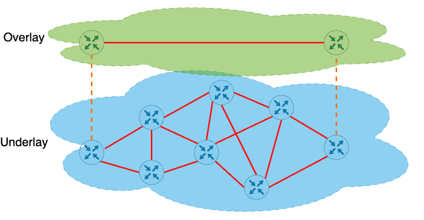
Components in a VXLAN environment
The components we will introduce make up VXLAN; as we introduce more items that interact with VXLAN, we will also introduce them. You will find the following in a VXLAN environment:
VXLAN Network Identifier (VNI): a 24-bit number that identifies the VXLAN segment. You can have up to 16 million VNIs
Virtual Tunnel EndPoint (VTEP): These are the tunnel endpoints, which can be physical or virtual, that encapsulate or decapsulate the VXLAN traffic.
The physical topology of a VXLAN environment is modeled after a CLOS network that contains several leaf switches, which could be thought of as access switches, and spine switches, which could be thought of as core switches.
What is VXLAN looking to solve
VXLAN has been around for a while, so why did we need yet another way to tunnel traffic? We can thank the cloud and multi-tenant data centers for this. Let’s take a trip in the Wayback machine—well, maybe not way back. Segmentation in the data center used to be done with VLANs, which are a tried-and-true way to segment. However, there is a fundamental problem with using them. Let’s take a peek at the diagram below, scaled down, of course.
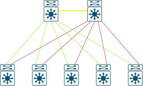
We are looking at a traditional core+distribution layer and an access layer. The network is configured with VLANs; we have some green and red links. This is Spanning-Tree blocking access to links due to the potential of looping the network. You are losing up to half of your available bandwidth due to links being in an STP-blocking state.
Network architects everywhere collectively in their design meetings said…

Then the one architect in the corner finally got the courage to speak his mind and wants to…
While on the surface, that seems like a great idea, all links will be forwarding. You can use equal-cost multi-pathing to ensure all links can route packets. VRF could be used for segmentation. Life seemed good. As always, though, something was missing. A few architects had that head-scratching moment. Again, all the architects met in a room, and a collective D’OH rang out. They forgot all about layer two traffic. In an all-IP network, how can you get layer two across the network? I mean I guess you could setup a VPLS network inside of your data center but come on, no one is that crazy….. right?!?!?!
VXLAN Enters the Chat
VXLAN is the best of both worlds. It allows you to transport Layer 2 frames over Layer 3 packets, thus removing the dependency for spanning trees and allowing you to have all links between leaf switches and spines active using ECMP. Since VXLAN is 24-bit vs VLAN 12-bit, this gives you 16 MILLION segments that you can use over 4096, which is just a tiny increase.
VXLAN Frame Format
Now, on to the geeky stuff, the VXLAN frame. The frame has two parts: the outer frame, which is the VXLAN frame, and the inner frame, which is your original payload. In the below image is what the VXLAN frame looks like, with the outer frame where the original (inner) frame would be and double click on the VXLAN header itself
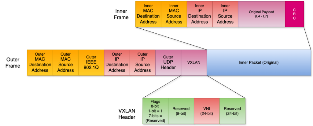
Let’s look at a few items from above:
- The outer mac and IP addresses are that of the VTEPs that are doing the encapsulation/decapsulation
- Source = encapsulating VTEP
- Destination = decapsulating VTEP
- The default port for VXLAN is UDP\4789
- In the VXLAN header:
- In flags, the
I Flagwill be set to 1, which means it is a valid VNI. The other seven flags are reserved - There are two blocks of reserved fields that wrap around the VNI
- One is 8-bit, and the other is 24-bit
- In flags, the
- The inner packet is the original packet the virtual machine sent before being encapsulated.
To see this in practice, let’s look at a ping between two VMs in the same VNI.
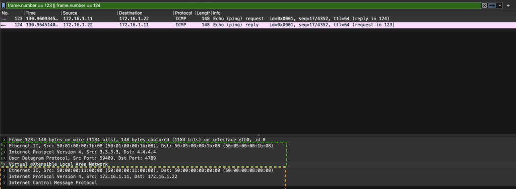
We first notice that Wireshark shows the inner (pre-VXLAN encapsulation) packet information. When we click on one of the frames, we see what looks like duplicate information, but we see the outer frame (green dotted) and inner frame (orange dotted).
Workload Communication
There are two ways in which VMs can communicate: Unicast VM-to-VM Communication and Unknown Host Communication. In Unicast VM-to-VM communication, the source switch will check to see if there is an entry in the Mac table and either in the arp cache or arp suppression cache for the destination VM, depending on how you have the VNI setup. Once it verifies that it knows the IP to MAC binding, the process is very similar to how two VMs communicate with each other outside of a VXLAN environment. In Unknown Host Communication, there is a broadcast mechanism to get the unknown mac address for the IP, but this is done over multicast.
Unicast VM-to-VM Communication
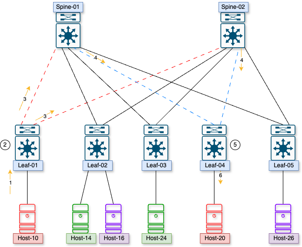
Breaking down the communication:
- Host-10 sends a packet destined to Host-20
- Leaf-01 gets the packet, looks up how to reach Host-20, and sees it must be encapsulated in VXLAN. The new destination is the VTEP on Leaf-04.
- The encapsulated packet is sent over both uplinks toward the spine switches, over the red dashed lines.
- The spines look at how to route the VXLAN packet and send it toward the VTEP on Leaf-04 on the blue dashed lines.
- Leaf-04 gets the packet and decapsulates it.
- Leaf-04 will then see that the Host-20 is on a local port and send the original packet to Host-20.
The only real difference here from a traditional packet is the VXLAN encapsulation. Everything else is the same.
Unknown Host Communication
Let us walk down memory lane before we get into how this works in VXLAN. When a host goes to communicate with another host that is on the same VLAN and the switch doesn’t know what port that host lives on, it will generate a broadcast packet and send to the broadcast mac-address of ff-ff-ff-ff-ff-ff, ff:ff:ff:ff:ff:ff, or ffff.ffff.ffff, depending on how you grew up writing out MAC addresses. The unknown host will respond to the ARP request. This will now allow the host to communicate with that once-unknown host. Now, how does this work in a VXLAN environment?
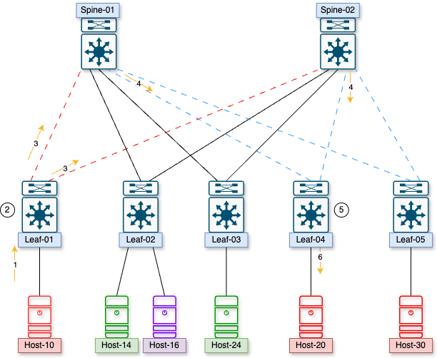
If host .10 wants to talk to host .20, how does Leaf-01 learn the host’s address on leaf-04?
- Host-10 sends a packet to Leaf-01, wanting to communicate with host-20
- Leaf-01 does not have an arp entry nor a MAC address for host-20, so it will initiate a broadcast over the VXLAN network that will go to the multicast group that is associated with that VNI
- VTEPs will periodically join and leave the multicast group that is assigned to the VNI
- A multicast packet is sent out of Leaf-01 toward Spine-01 and Spine-02
- The multicast packet is delivered to all VTEPs that belong to that VNI
- The switches decapsulate the VXLAN packet and send the arp request out to all ports that belong to that VLAN as normal
- The correct host responds, and there is a unicast VXLAN packet sent back to the original switch in this instance, letting it know where that host is
- ARP and MAC entries are updated.
Since we are all geeks at heart, let’s look at this in pcap form
The Multicast ARP from the source switch
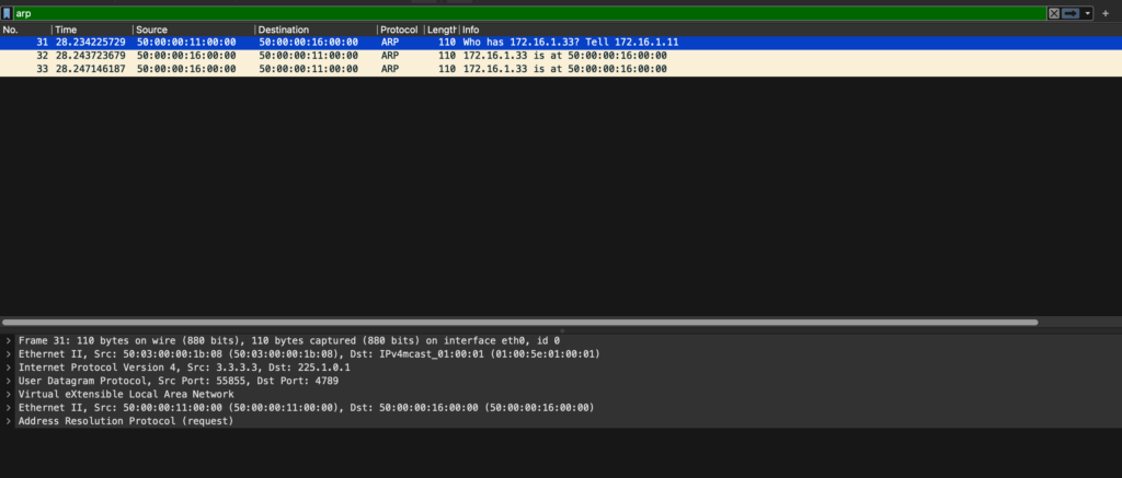
We see that it is going to a multicast group of 225.1.0.1, and all VTEPs that have this VNI configured will get this packet.
The response from the device to the host
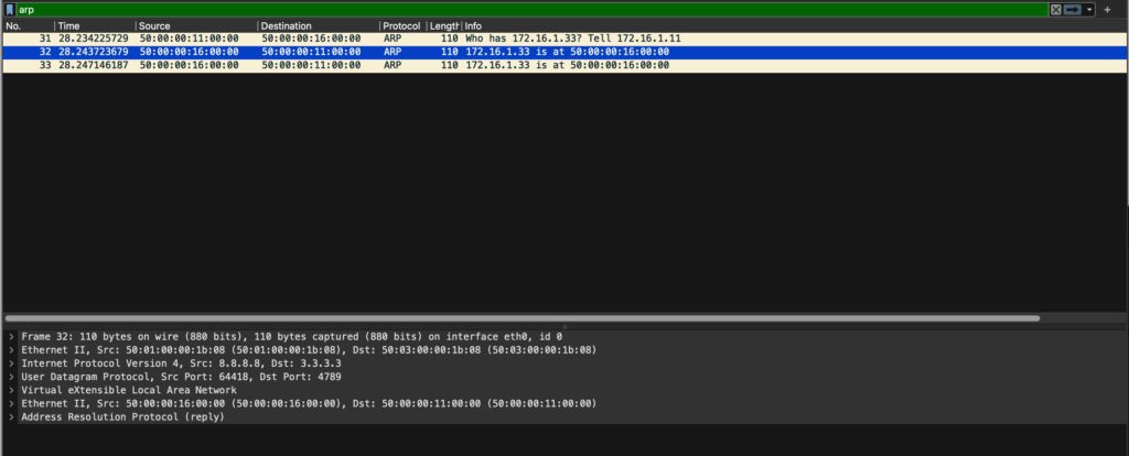
On the source switch, we get a unicast reply from the VTEP that has this host on it. When this is received, the information is added to the mac and arp tables so that it can be treated just like the unicast flow from above.
Basic Deployment Scenarios
We will explore two basic deployment scenarios here, one we saw in our communication examples. The VTEP in that deployment scenario is a physical hardware switch, but we could also have our virtual switches be the VTEPs. I recommend this if you really like dealing with your infrastructure people, and they never give you any heartburn over networking issues. If you want to throw caution to the wind, this deployment would look like this.
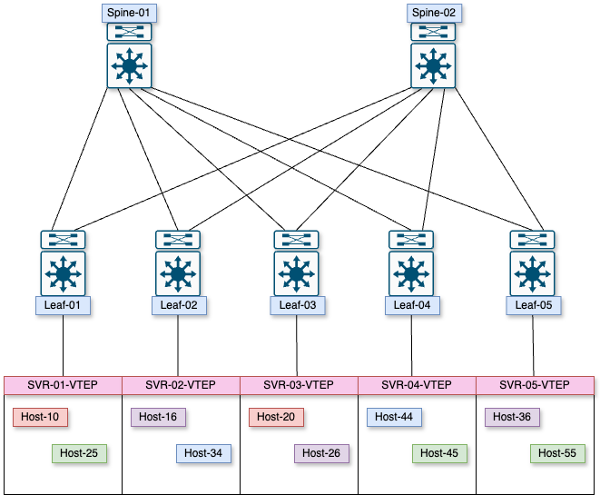
Instead of living in hardware, the VTEPs live in software on the virtual host, which could be from a networking vendor or the virtual host’s own switch.
VXLAN Gateway
The other deployment scenario is if you want to leave the VXLAN environment and enter a non-VXLAN environment. A device will translate VXLAN to VLAN and vice versa so packets from the legacy network can return to the VXLAN environment. Like the previous example, the VTEPs can be physical or virtual. The only change here is that we are adding a device that will map VXLAN to VLAN.
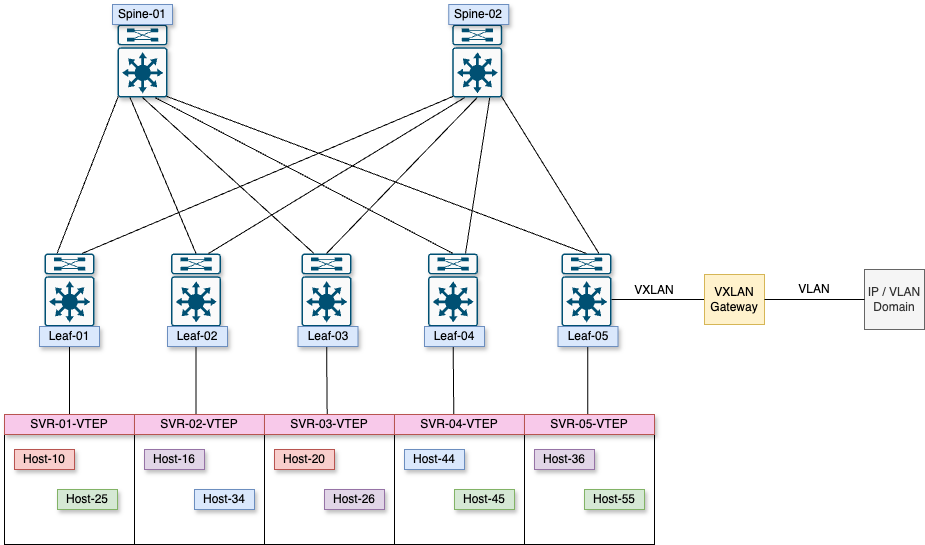
That is VXLAN in a nutshell. It has been a while since I had to play around with it, and it was an excellent refresher from which to get back into it. How did you learn VXLAN for the first time? Let me know in the comments below or on my socials. One more thing I want to touch on before we get to building is multicast basics. This will give us the foundation to deploy the fabric our manager wants us to. See you on the next one!